Regions
1. Overview
One of the most important features of the Aquarius's device modelling capabilities is the ability to define the geometry of a device's regions using the Rectangle, Rounded Rectangle, Polygon and Import from CSV drawing functions. After the outline geometry of a device has been drawn, the regions properties can be defined and material properties assigned to them.
2. Usage Instructions
2.1. Rectangle, Rounded Rectangle and Polygon
To define a region using a cursor:
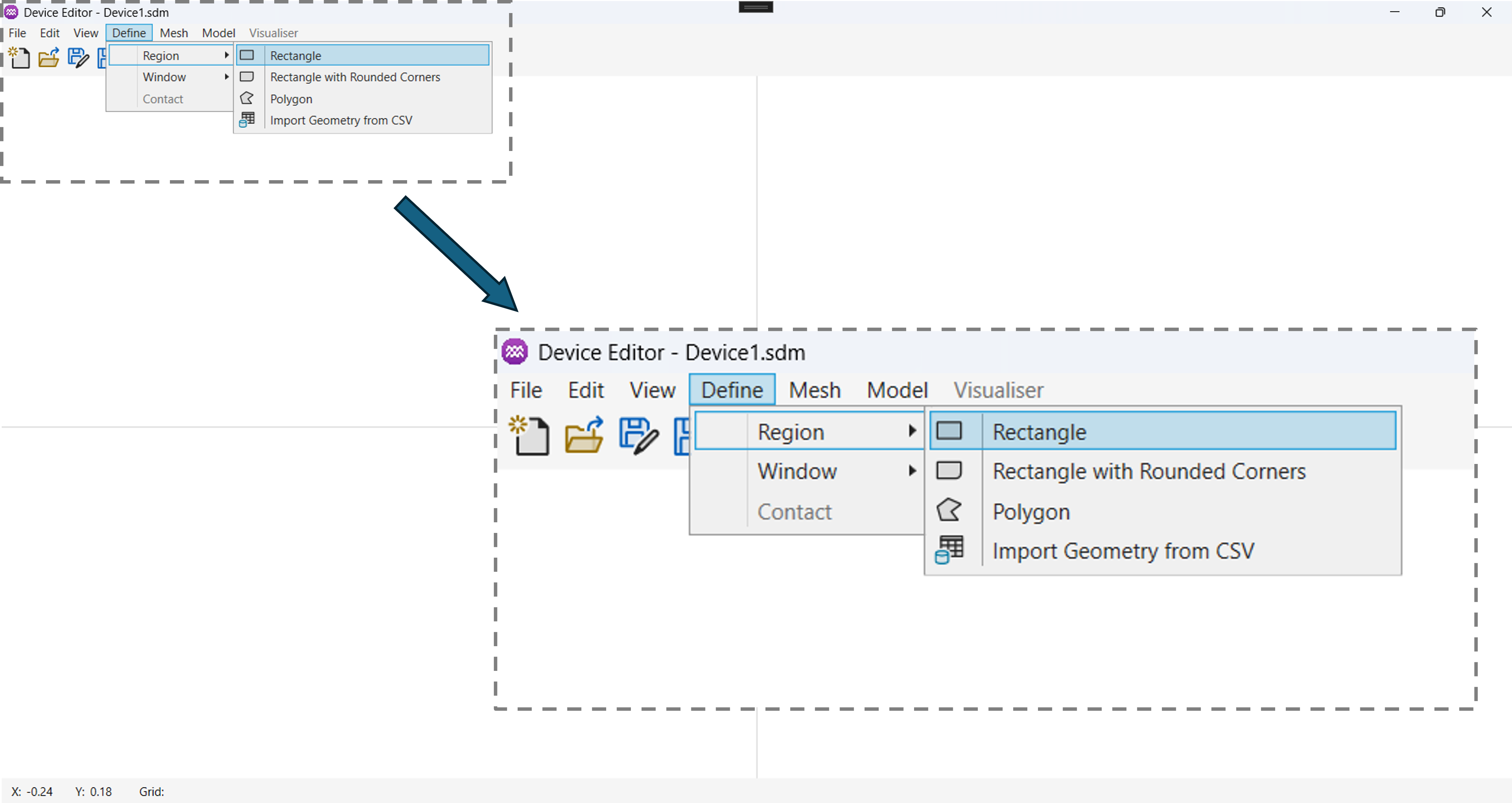
- From the Menu, select
Define->Regionand select the type of geometry you would like to define (Rectangle, Rounded Rectangle or Polygon).
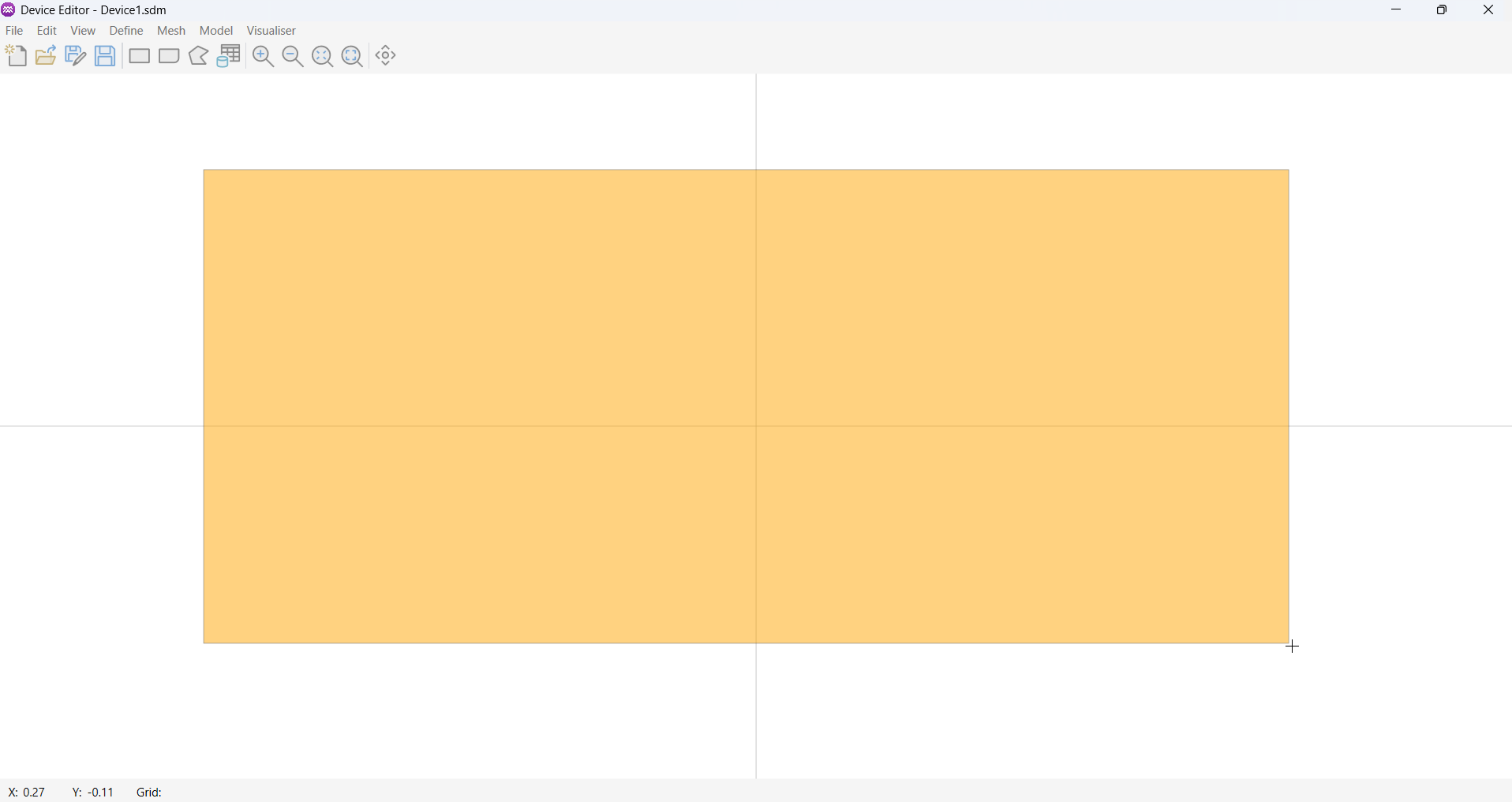
- Use your cursor and mouse buttons to define the region shape. Or if importing geometry from a .csv file, select the file you want to use.
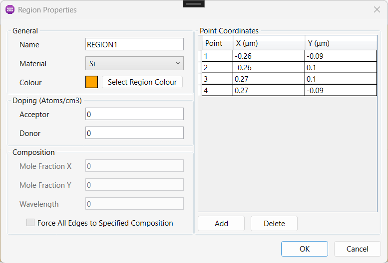
- Once the region's shape has been defined the region properties dialog box will appear. Use this dialog to set the region's properties.
2.2. Import Geometry from CSV
The Import Geometry from CSV option is particularly useful when working with geometries extracted from experimental data—for example, outlines digitised from SEM images, or data generated by external CAD or metrology tools.
This is particularly useful if importing geometry data obtained for example from a (SEM/TEM - ai which is right?) image.
If defining a region from a .csv file:
- From the Menu, select
Define->Region->Import Geometry from CSV.

- A file dialog will appear, select the csv file you wish to import.

- Once imported, the editor will automatically create the polygonal region and open the Region Properties dialog.

All coordinate values must be specified in centimetres (cm). Points must be listed in the correct sequential order around the region boundary (clockwise or counter‑clockwise). The polygon will be automatically closed do not repeat the first point at the end of the file. The tool assumes a simple polygon; self‑intersecting shapes are not supported.
2.2.0.1. Example Geometry CSV file
0.0E-3, 1.0E-3
0.7E-3, 0.7E-3
1.0E-3, 0.0E-3
0.7E-3, -0.7E-3
0.0E-3, -1.0E-3
-0.7E-3, -0.7E-3
-1.0E-3, 0.0E-3
-0.7E-3, 0.7E-3
This example produces a clean 8‑point polygon (octagonal‑like shape) that imports correctly, follows the clockwise/counter‑clockwise rule, and does not repeat the starting point.
3. Parameters
3.1. General
| Name | Description | Unit |
|---|---|---|
Name | A unique identifier for the region. | - |
Material | Used to define the material properties of the region. | - |
Colour | Used to define visual colour of the region (Not used in the solver). | - |
The properties of these materials can be fully customised by the user during setup of the device model. There are two general types of semiconductor can be defined, namely:
- Constant Bandgap (e.g. Si, GaAs, SiC)
- Variable Bandgap (e.g. AlGaN, AlGaAs).
3.2. Doping
| Name | Description | Unit |
|---|---|---|
Acceptor | Used to define the acceptor doping concentration in the region. | cm-3 |
Donor | Used to define the donor doping concentration in the region. | cm-3 |
3.3. Composition
After a region has been defined, a constant material composition can be assigned to that region. For ternary alloys a single mole fraction X specifies the relative composition of the two constituent binaries. For quaternary alloys two independent mole fractions, X and Y, are required. The remaining fraction is determined by normalisation.
3.3.1. Ternary Material
Using AlGaN as an example.
where:
- = mole faction of Al
3.3.2. Quaternary Material
Using InAlGaN as an example.
where:
- = mole faction of In
- = mole faction of Al
| Name | Description | Unit |
|---|---|---|
Mole Fraction X | Used define the mole fraction X. Value range between 0 and 1. | - |
Mole Fraction Y | Used define the mole fraction Y. Value range between 0 and 1. | - |
For quaternary alloys, each mole fraction must lie in the range and . In addition, the sum of the mole fractions must satisfy . If this condition is violated, the composition is physically invalid and will be rejected.
3.4. Point Coordinates
Once a region has been defined, users can modify its geometric points to adjust its shape. Users can add, edit, and delete points as needed.
- Editing Coordinates: Modify the region’s coordinates by directly editing the values in the table cells.
- Adding a Point: Click the
Addbutton to insert a new point. - Deleting a Point: Select the point to be removed and click
Delete.
The region points are specified in a clockwise direction, so ensure they remain in the correct order to avoid inverting the shape.
Each point has two parameters.
| Name | Description | Unit |
|---|---|---|
X | Used to define the X coordinate. | Microns |
Y | Used to define the Y coordinate. | Microns |