Meshing Grid
Overview
To create a triangulated finite element model of a device, the user must define the structure and layout of the mesh. A mesh is composed of triangles formed by triangulating a set of nodes in 2D space. These nodes are positioned at the intersections of mesh lines, which are arranged in orthogonal groups along the x and y directions.
The process begins with the definition of a grid, where the user specifies horizontal and vertical line groups to form a template for the mesh. This grid structure allows for the addition of extra nodes in regions of interest, providing higher mesh resolution in areas where more precise simulation results are required, for example at the semiconductor oxide interface. The intersections of these orthogonal lines, along with the boundaries of the regions being modelled, define the geometric node points that form the basis of the finite element mesh.
Usage Instructions
To define a rectangular meshing grid:
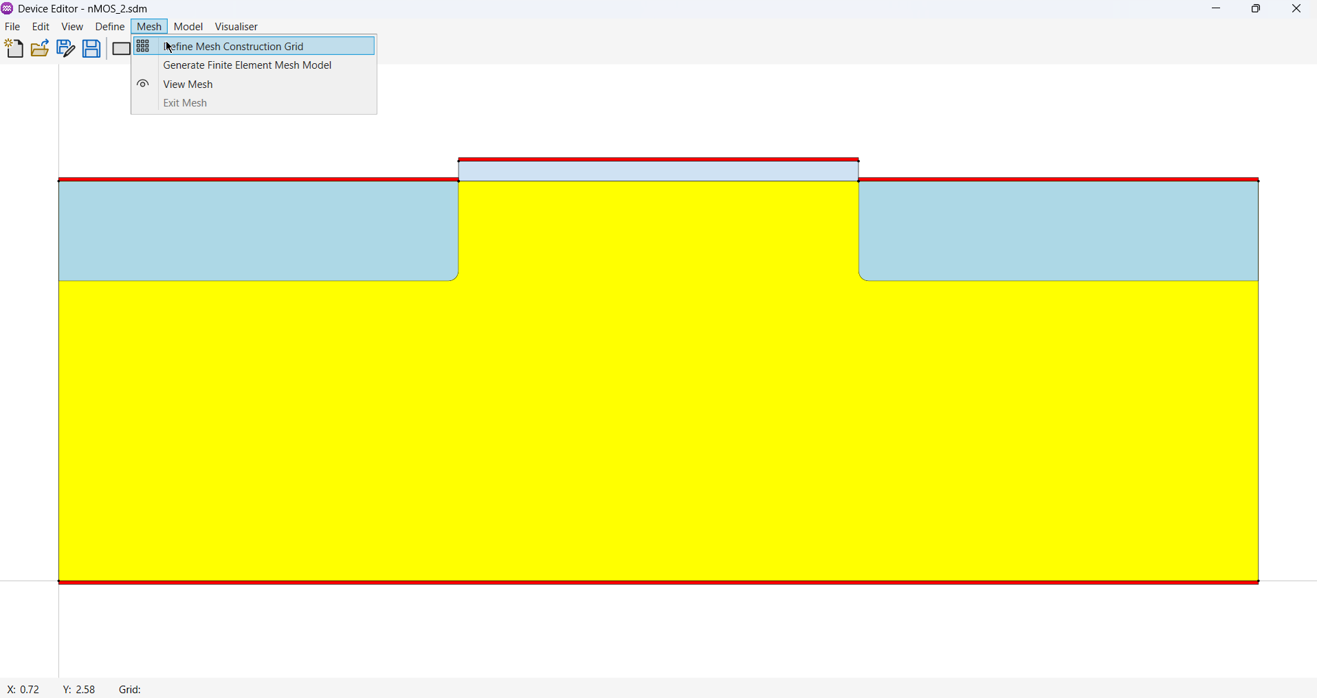
- From the Menu, select Mesh -> Define Mesh Construction Grid. This will open a properties dialog.
- Click the
Addbutton to create a new group of grid lines.
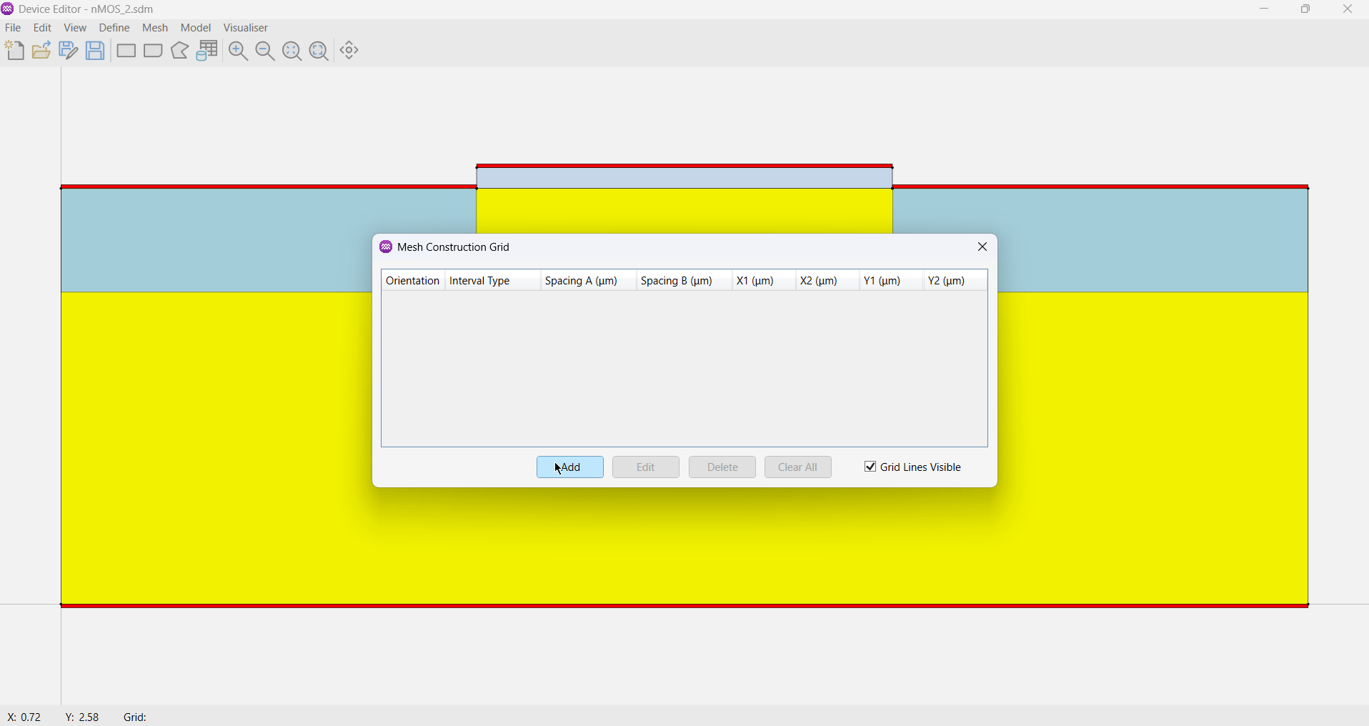
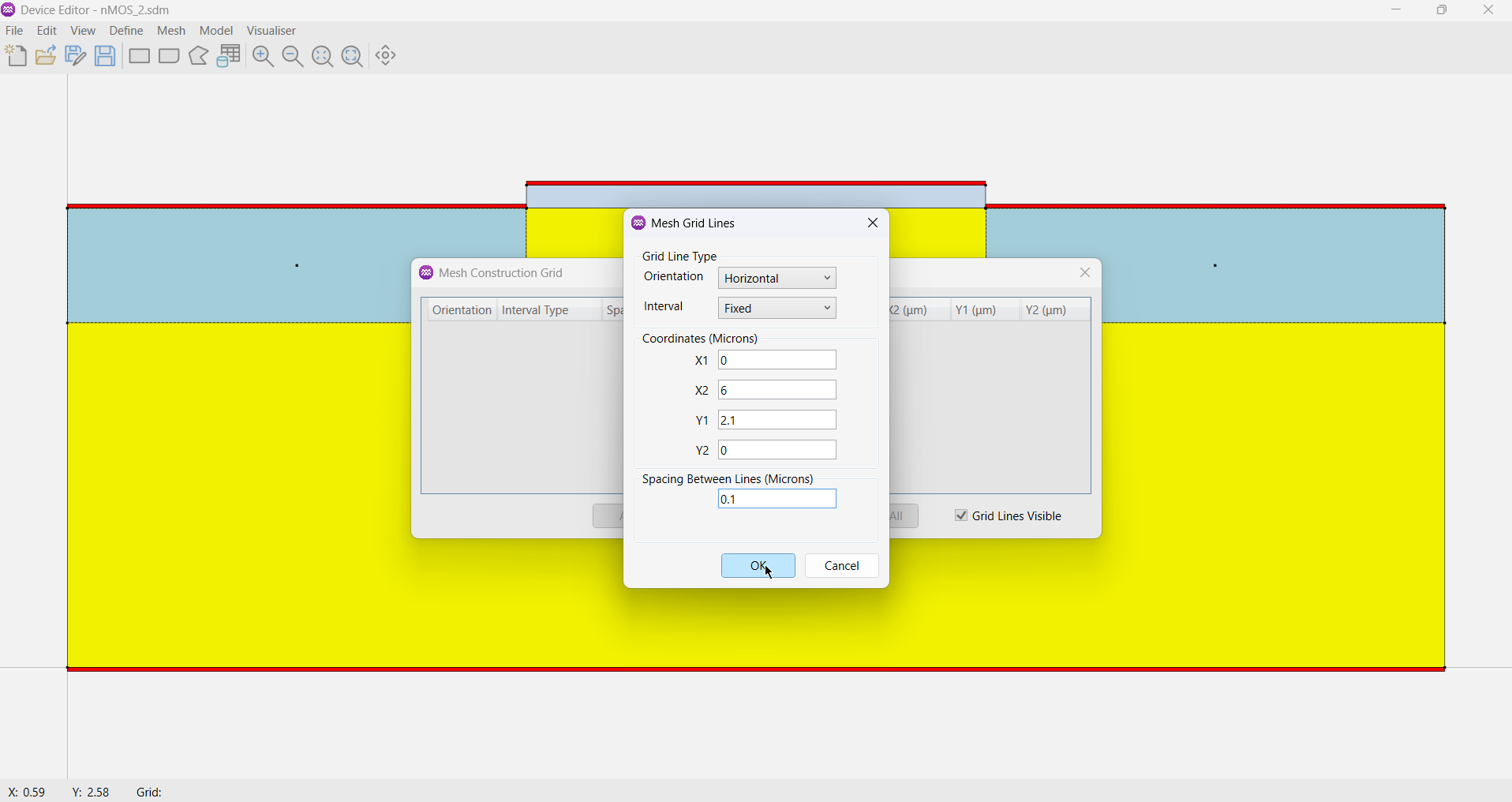
- In the dialog box, define the properties of the grid line group.
- Specify the rectangular area using X and Y coordinates, for example, (0,0) to (5,5).
- Set the spacing between the grid lines.
- The grid lines will appear overlaid on the device structure.
- Click
OKto generate the collection of grid lines over the defined area.
Repeat this process for both the horizontal (X) and vertical (Y) directions until a suitable meshing grid of intersecting lines is achieved.
Close the Mesh Construction Grid window by clicking the X in the top-right corner.
Parameters
Each collection of grid lines is defined by the following parameters.
Grid Line Type
| Name | Description | Unit |
|---|---|---|
Orientation | Used to specify the direction of the grid lines. Options: [Horizontal, Vertical] | - |
Interval | Used to determine the spacing pattern for the grid lines. Options: [Fixed, Graded] | - |
Coordinates
| Name | Description | Unit |
|---|---|---|
X1 | The x-coordinate of the lower-left corner of the rectangular area. | Microns |
X2 | The x-coordinate of the upper-right corner of the rectangular area. | Microns |
Y1 | The y-coordinate of the lower-left corner of the rectangular area. | Microns |
Y2 | The y-coordinate of the upper-right corner of the rectangular area. | Microns |
Spacing Between Lines
| Name | Description | Unit |
|---|---|---|
Spacing | If Interval = Fixed, this sets a uniform spacing between all lines. | Microns |
Top | If Interval = Graded and Orientation = Vertical, this sets the spacing at the topmost coordinate. | Microns |
Bottom | If Interval = Graded and Orientation = Vertical, this sets the spacing at the bottommost coordinate. | Microns |
Left | If Interval = Graded and Orientation = Horizontal, this sets the spacing at the leftmost coordinate. | Microns |
Right | If Interval = Graded and Orientation = Horizontal, this sets the spacing at the rightmost coordinate. | Microns |