Mesh Generation
Overview
Once the initial meshing grid has been defined, this command will generate the nodes at the intersections of those lines and triangulate them to form the finite element mesh. The Delaunay algorithm is used and additional checks are made to ensure optimal triangle shapes, reducing narrow or poorly shaped elements that can impact simulation accuracy.
Usage Instructions
Before creating a finite element device model, it is important to ensure that at least one region is defined and a suitable meshing grid has been specified.
To generate a finite element model:
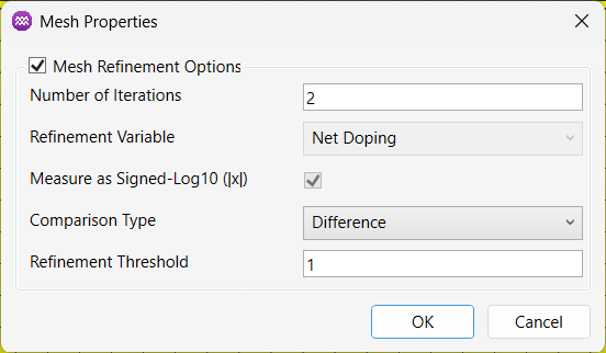
- From the Menu, select Mesh -> Generate Finite Element Mesh Model. This will open the mesh properties dialog.

- If automatic mesh refinement is required, enable the Mesh Refinement Options checkbox. By default, this option is disabled. When enabled, you can adjust the mesh refinement settings as needed.
-
Once you are satisfied with the settings, click
OKto generate the mesh. -
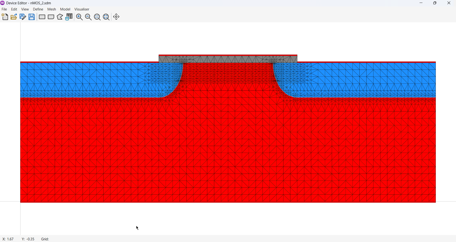
Depending on the complexity of the device model and the meshing grid, the generation process may take some time. The progress of the mesh generation will be displayed in the status window in the centre of the screen. Once complete, the finished FE model will be displayed. The P and N regions of the device will also be plotted, highlighting the position of the metallurgical junction, which is the point where the net doping concentration is zero Atoms/cm³.
Parameters
| Name | Description | Unit |
|---|---|---|
Number of Iterations | Used to specify the number of refinement cycles. | - |
Refinement Variable | Used to specify the physical property used for refinement. Options: [Net Doping] | - |
Measure as Signed-Log10 | When checked, the refinement variable is measured on a logarithmic scale with sign. | - |
Comparison Type | Used to define the method for comparing refinement values. Options: [Difference, Percentage Difference] | - |
Refinement Threshold | Used to set the threshold value for refinement. | - |