Transient Sources
1. Overview
Used when performing a time-dependent simulation. These components provide time-varying current or voltage sources that drive a circuit with a defined waveform over time. They are ideal sources, meaning their output is defined entirely by the specified waveform, regardless of the connected load.
There are four types of transient waveforms namely:
- Piecewise Linear (PWL) Waveform.
- Allows the definition of custom, non-periodic waveforms by specifying a series of time-value pairs, creating a piecewise linear signal. This is useful for complex waveforms that cannot be captured by simple sine, triangle, or square waves.
- Sine Wave.
- Generates a sinusoidal current or voltage signal.
- Triangle Wave.
- Generates a linear, periodic triangular waveform.
- Rectangle Wave.
- Generates a square wave with programmable high and low states, as well as on/off times.
2. Parameters
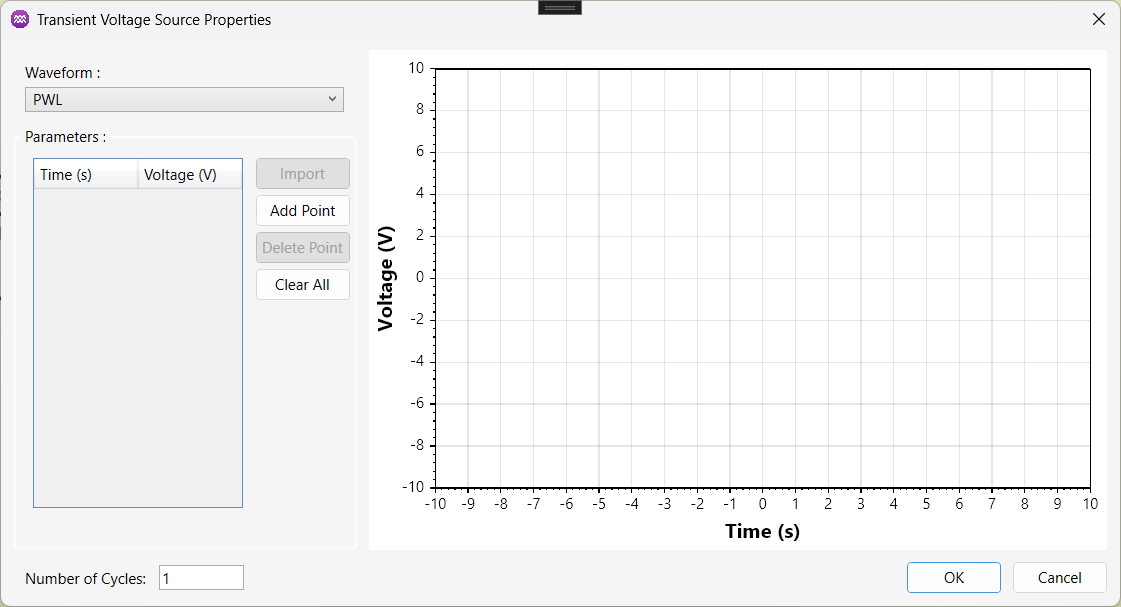
2.1. PWL
| Name | Description | Unit |
|---|---|---|
Times | A list of time points defining the waveform. | seconds |
Values | A list of corresponding voltage or current values at each specified time point. | V or A |
Number of Cycles | The total number of cycles of the waveform the source outputs before stopping. | - |
2.2. Rectangle
| Name | Description | Unit |
|---|---|---|
Min Voltage/Current | The lower level of the rectangular waveform. | V or A |
Max Voltage/Current | The upper level of the rectangular waveform. | V or A |
Frequency | The number of cycles the waveform completes per second. | Hz |
Theta1 | The phase angle at which the waveform begins rising from the minimum to the maximum value. | Degrees |
Theta2 | The phase angle at which the waveform reaches its maximum value. | Degrees |
Theta3 | The phase angle at which the waveform begins falling from the maximum to the minimum value. | Degrees |
Theta4 | The phase angle at which the waveform returns to its minimum value. | Degrees |
Number of Cycles | The total number of cycles of the waveform the source outputs before stopping. | - |
2.3. Sine
| Name | Description | Unit |
|---|---|---|
Max Voltage/Current | The peak amplitude of the sine waveform. | V or A |
Frequency | The number of cycles the waveform completes per second. | Hz |
Theta | The phase angle that determines the initial position of the waveform within its cycle. | Degrees |
DC Component | A constant offset added to the entire waveform, shifting it vertically. | V or A |
2.4. Triangular
| Name | Description | Unit |
|---|---|---|
Min Voltage/Current | The lower level of the triangular waveform. | V or A |
Max Voltage/Current | The upper level of the triangular waveform. | V or A |
Frequency | The number of cycles the waveform completes per second. | Hz |
Theta Start | The phase angle that determines the initial point within the waveform's cycle. | Degrees |
3. Usage Instructions
tip
For instructions on adding a component to the simulation circuit, click here.
The steps below show how to configure the component effectively.
3.1. Adding Points
- Click
Add Pointto add individual points, each point is a time-voltage or time-current value. - Alternatively, you can
Importa list of values from an external CSV file.
3.2. Remove Entries
- Select a value from the list and left-click the cell to modify it's value.
- Use
Delete Pointto remove a selected entry. - Use
Clear Allto remove all values from the list.
3.3. Adjust the Number of Cycles
- To adjust the number of cycles for the waveform, edit the value in the text box.
3.4. Apply the Configuration
- Once all parameters are set, click
OKto save the changes. - Click
Cancelto discard any changes and close the window.